Radio has as firmly established itself in the life of the nation as has the automobile. In the transmission and reception of radio are involved physical principles that are intensely interesting, yet difficult to teach. It is doubtful whether these principles can be made clear to any except a few brilliant students in discussions based on the textbook and in blackboard illustrations alone. The ordinary receiving set is interesting enough to the student, but as an educational apparatus it is of small value. It cannot make real to the student the electromagnetic wave that carries the music and speech from the broadcasting station, and without which there can be no radio. The nature of the electromagnetic wave is thus the fundamental thing, and unless the student knows something about it, his knowledge of radio cannot be considered fundamental.
The old-fashioned coherer outfit used in demonstrations for twenty-five years and more is quite inadequate as means for teaching the fundamentals. It is little better than a receiving set of standard pattern would be for the purpose. To be sure, it includes transmission as well as reception, but the important ideas of resonance and tuning remain obscure because, with such a set, tuning is out of the question.
Recent developments, and the perfection attained in the manufacture of certain types of three-electrode vacuum tubes, have made possible the design of an apparatus which meets most of the requirements that can be set up for a demonstration apparatus which will really teach the fundamentals of radio. For several years the writer has kept his attention on these requirements, with the objective in view of designing an apparatus which should show the various phenomena associated with electromagnetic waves within the confines of the classroom; which should be so simple to operate that any teacher could successfully make the demonstrations; and which should be sufficiently powerful that the various effects of the waves could be convincingly shown without delicate apparatus. Such an apparatus has been developed, and the experiments that can be performed with it are among the most astonishing that can be shown in physics. The apparatus provides not only for impressive classroom demonstrations. The teacher who believes in imparting scientific knowledge to the layman-the average citizen of his community-can use it in giving a popular lecture that will be most entertaining and instructive. He will find, incidentally, that engaging in such activities will be an effective method of getting in friendly touch with the community in which he labors.
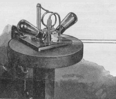
The apparatus consists of three basic units: the high frequency electron tube oscillator with two sets of sending antennae, the power supply unit, and the tunable receiving antenna with indicating lamp. The high frequency oscillator comprises a simple circuit capable of generating oscillations of fixed frequency of about 100,000,000 cycles per second. (See Fig. 1.) Two power tubes of type UX210 are employed. These were
chosen because they are standard and can be purchased from any good radio dealer, and because, of the common tubes, the UX210 is the best oscillator. Ample power is thus delivered into the oscillating circuit. The "sending" unit, consisting of tube sockets, condensers, inductive loop and accessory units, is mounted on a small Bakelite base 11 cm. by 16 cm. With tubes in place, its extreme width is 30 cm. and height 14 cm. It is a most compact little unit. At the back is a triple connector socket. The plug which fits this socket is connected to the power supply unit. To operate the "sending" unit, the power supply unit is connected to a 110 volt 60 cycle source, and the multiple connector plug to the "sending" unit. As soon as these connections are made, the "sending" unit is oscillating.
The power supply unit consists of a transformer with several secondary windings. One of the windings is used for lighting the filaments of the two vacuum tubes, and another for supplying the plate voltage. The latter is about 500 volts, and although caution in handling is advised, the circuits are so well insulated that, with ordinary care, there is no hazard whatever in the use of the apparatus.
The "sending" apparatus includes two sets of radiating antennae. One pair is attached directly to the terminals of the oscillator loop, and extend outward horizontally. The vertical antennae are connected to a coupling loop which may be variably coupled with the oscillator loop. Either pair of antennae may be used alone, or they may be used simultaneously, as described below.The third unit of apparatus is the receiver. This is astonishingly simple. It consists of a tunable linear oscillators straight conductor of variable length-in the middle of which a small low-voltage incandescent lamp bulb is connected. Lighting of the filament is an indication of reception.
Included also in this group of apparatus is a small neon glow lamp, which is an excellent indicator of potential, and with which potentials existing at various points on the sending or receiving antennae may be explored.
The experimental procedure is very simple. 'With it the following interesting experiments, as well as others that will suggest themselves to the experimenter, can be performed.
1. Starting the Oscillator. Two UX210 tubes are inserted in the tube sockets. Connect the sending unit to the power unit by the triple connector plug. Then connect the power unit to the 110 volt 60 cycle supply. The sending unit should now be oscillating. To test whether it is oscillating, touch the exposed metal connected to the plate terminal of either tube with a piece of metal, or the graphite tip of a lead pencil, or the electrode of the neon test lamp. If the circuit is functioning, sparks appear at the contact, and the test lamp glows strongly. When the neon lamp is touched to the oscillator loop at the mid- point, where the plate supply voltage is led in, it will not glow at all, or only slightly. The reason is that this is a point of low potential in the oscillating circuit. It makes for great convenience and successful results in these demonstrations if the sending unit is supported on a wooden tripod stand. The presence of large masses of metal near the set should be avoided.
2. Measuring the Wave-Length. When the oscillator is functioning, a quantity of electricity is surging back and forth at high frequency in the oscillator loop. The rate at which this surging takes place is determined by the inductance and capacitance of the loop, and the distributed capacitance of the conducting materials to which the ends of the loop are fixed. The oscillation of the charge in the loop constitutes a current of high frequency, associated with which there is an oscillating magnetic field which extends through the loop. At the instant the current reverses, the ends of the loop are at a large potential difference, and the current is zero. This condition gives rise to an electrostatic field across the ends of the loop. At the instant the current is maximum, the electrostatic field is zero. We may now trace the complete cycle, referring for greater clearness to Figs. 2-6 inclusive. We shall, in this process, not go into the details of functioning of the circuit, but take for granted that the vacuum tubes, supplied with power from the line, sustain the oscillations which we are examining more closely. In the figures the circular part represents the oscillator loop, which may be considered as having principally inductance; the parallel lines represent the capacitance associated with the loop.
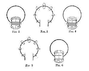
Fig. 2 represents conditions at some instant; let us consider it the beginning of a cycle. There is no current in the loop; but the charges (in terms of the usual convention) are at maximum displacement, so that we have maximum potential difference across the capacitance. Consider the right-hand side positive, the left, negative. The electrostatic force is maximum, with its direction as shown. At the instant we are considering, current begins to flow, because of the large potential difference between two points connected by a conductor-in this case the loop.
In Fig. 3 the current has reached maximum value. With the current are associated magnetic lines of force which began to appear at the instant the current started to flow, and which have reached maximum value now. The lines are at right angles to the loop, coming out of the paper within the loop, passing into the paper outside the loop. During this time the magnetic lines, which are closed figures approximating circles about the loop, are expanding outward with the velocity of light. The accompanying electrostatic field, everywhere perpendicular to the magnetic, and travelling with the latter, has been decreasing, and at the instant represented in Fig. 3, has vanished.
Because of inductance in the circuit, the current continues to flow in the same direction, which results in an increasing positive charge at the left, and negative on the right side of the condenser, as in Fig. 4. A maximum is finally reached, de- pending on the characteristics of the circuit. The electrostatic field incidentally is not limited as shown by the lines in the figure, but becomes established theoretically to an infinite distance with the velocity of light. When the current is maximum, the electrostatic field between the plates is zero.
Again, because of inductance, the current continues until the condition of maximum charge is reached, as in Fig. 6, which is identical with Fig. 2. We have now traced through a complete cycle of the oscillation, which is, in its simplest terms, an alternating current in the loop at exceedingly high frequency. Associated with this current are electrostatic and electromagnetic lines of force, mutually at right angles, traveling outward at the velocity of light. This traveling electromagnetic field constitutes a train of electromagnetic waves. One wave-length corresponds to a complete cycle of oscillation, represented in Figs. 2 to 6, as explained. Since the waves travel with the velocity of light, or 300,000,000 meters in one second, the length of one wave is the distance the wave travels during the time of one oscillation. In the apparatus which we are describing, this wave-length is-as we shall directly determine by measurement about 3.2 meters. Thus the time of one oscillation is 3.2/300,000,000 seconds, and the frequency is 300,000,000/3.2 or about 94,000,000 cycles (94,000 kilocycles) per second.
The motion of the electromagnetic field outward from the oscillating circuit represents a radiation of power, sustained by the power supply unit through the agency of the vacuum tubes. Such a loop is not a good radiating means, yet it is possible to detect the radiation, and to measure the wavelength.
To detect the radiation, we make use of the fact that if an electric circuit of proper inductance and capacitance is so placed relative to the oscillator that the electrostatic and magnetic lines which are radiated by the latter can induce a current in the former circuit, it will respond by having an oscillating current set up within it. The second circuit consists of a single loop, connected to a variable condenser of small capacitance. This condenser can be adjusted until the time of one oscillation in the circuit is the same as that in the oscillator. The combination of inductance and variable capacitance is called a wave-meter. When the wave-meter is held with its loop parallel to and any- where within 30 cm. of the oscillator loop, and the condenser adjusted to the proper value, strong oscillations are set up in the wave-meter circuit. This adjustment is called tuning, and is identical with the tuning of an ordinary radio receiver. When the circuit is tuned it is said to be in resonance. To determine when the circuit is tuned we attach near one end of the loop the neon detector bulb. The bulb glows at resonance. Another indicator is a small flashlight bulb clipped across a short section (about 3 cm.) of the wave-meter loop. At resonance, the bulb lights brightly; in fact, unless one is careful, the bulb is easily burned out. The wave-meter has a 0-100 scale; a calibration chart supplied with the instrument converts scale readings to wave-length in meters.
3. Standing Waves on Wires. Another method of measuring wave-length is by the Lecher wire method. Standing waves are generated on a pair of parallel wires by coupling the oscillator to a small loop of copper rod, as shown in Fig. 1, to which the wires are connected. The loop is plugged into the sockets at the front of the oscillator, and two No. 24 bare copper wires are attached by twisting, one to each end of the loop. The wires are then stretched out parallel over any available distance, preferably greater than 5 meters, and supported at the opposite end by twisting them around a stick of dry wood, glass or other insulator, and clamping the latter on a rod, or otherwise holding it so that the wires are parallel and taut. The glow lamp is now so mounted in the oscillator loop that it will glow brightly when the power is turned on, thereby indicating that the current is oscillating. Standing waves of potential and current are established on the wires. These waves become especially pronounced if the parallel wire system is "in resonance," i.e., if the length of the wires bears a definite relation to the wavelength. In case the ends of the wires are "open," a reversal in phase on reflection takes place, as in an open organ pipe; the open ends become points of maximum potential variation. If the ends are "closed," or bridged by a conductor, the potential variation must become zero, and these points will then be potential nodes. A conducting wire bridging the parallel wires is, in fact, used to "tune" the system to resonance. This is moved from the open ends towards the oscillator until a glow lamp, connected across the wires about 80 cm. away, glows most brightly. The condition of resonance is also indicated by the glow lamp connected to the oscillator loop; this shows sudden diminution in intensity when the nodal point is bridged. The other nodal points, at which zero values of potential exist between the wires can now be located by exploring the wires with a second glow lamp, bridging the latter across the wires. The lamp remains dark in regions of small potential difference, and bright where the potential difference is large. The nodal points of potential can be even more accurately located by sliding another conducting bridge along the parallel wires. As each nodal point is passed, the glow lamp in the oscillator will suddenly "wink," or grow dimmer; possibly it may go out. This behavior of the glow lamp is due to the energy which is being abstracted from the oscillator, which is maximum at resonance. The distance between adjacent points of zero and maximum potential, respectively, is a half wavelength of the electromagnetic waves produced in the oscillator.
4. Transmission and Reception of Radio Waves. The electromagnetic waves which originate in this apparatus are found by measurement (see preceding section) to be of the order of 3.2 meters in length. To increase the energy radiation from the oscillator, the latter is supplied with radiating antennae. These consist of two copper-plated brass tubes, one end of which is pro- vided with a tapered plug for both mechanical support and electrical connection. As a first experiment, plug the antennae horizontally into the sockets at the lower terminals of the oscillator loop. When the oscillator is started, the electrical surges travel to the ends of the antennae, and there is set up in the system a "standing wave" with maximum potential at the ends and maximum current at the mid-section, which is the oscillator loop. With the neon test bulb the potential distribution can be explored; and the current distribution is found by means of the small incandescent bulb, "clipped" across a centimeter or two of the oscillator loop, or of the antennae. Several test bulbs may be used simultaneously.
With the wave-meter we find that connecting the antennae slightly increases the wave-length. Knowing this wave-length, we can construct a linear oscillator to resonate at the frequency corresponding to this wave-length. The length of the oscillator (in the middle of which the flashlight bulb is inserted) is roughly adjusted to one-half the wave-length. If properly tuned, this "receiver," held horizontally about a meter away, responds to the waves being radiated, and the bulb glows brightly; fine adjustment may be made to the setting at which the bulb is brightest. The length of the "receiver" is another check on wave-length. Under good conditions, the lamp glows at several meters from the transmitter.
Receiving antennae in which several flashlight bulbs (about 7) are inserted are particularly effective in showing the cur- rent distribution in such an oscillator. A straight copper wire of the same length, on which several neon test lamps are distributed, shows the voltage distribution.
5. Demonstration of Polarization of the Waves. When the receiving antennae are parallel to the sending antennae, there is response; as the former are turned relative to the latter, the response weakens, and becomes zero at 90'. This shows polarization of the radio wave.
A vertically polarized wave of variable intensity can easily be produced. Plug the "coupling loop" into the socket in the base of the transmitter so that its single turn can be adjusted 'in position relative to the oscillator loop, by turning in the socket. Plug the one antenna into the upper end of the coupling loop, and the other into the socket from beneath. To do this, allow the base to protrude over the edge of the stand or table. Using any one of the receiving antennae mentioned, it will be found that there is maximum response with the "receiver" vertical, and zero response when it is horizontal.
6. Change in Power Radiated with Change in Coupling. With the single bulb antennae held vertically in one hand, change the coupling by turning the coupling loop in the socket. When the two loops are far apart, i.e., when the coupling loop makes a large angle with the oscillator loop, response is weak; when the loops are parallel, response is strong. This shows that more energy is "fed into" the antenna, and radiated, with close coupling.
7. Measurement of Electromagnetic Field Intensity. Connect a thermo-galvanometer to the receiving antennae in place of the flashlight bulb. Deflection of the pointer is proportional to the square of the current, hence to the energy in the linear oscillator, which must be roughly proportional to the energy radiated to the point at which the receiver is located. It is instructive to take readings of the meter at different distances from the transmitter, with the receiving antennae parallel to the transmitting antennae, and to take readings, at a given distance, as the angles between receiving and transmitting antennae are changed.
Exploration of the electromagnetic field in the standing waves on the parallel wire system described in Section 3 may be simply and easily accomplished by moving the thermo-galvanometer along, but not touching the wires. In this manner the maximum and minimum points of electric force are quickly found and demonstrated.
8. Composition of Two Plane Polarized Waves. This experiment is a beautiful illustration of a polarized wave of great intensity, composed of two plane polarized waves at right angles to each other. To perform the experiment, both sets of antennae -horizontal and vertical-are used simultaneously. The oscillator is started. The receiver responds in either position parallel to one of the antennae. It responds with great intensity at 45', in the position bisecting the angle between the antennae; but in the other 45' position, at right angles to the first, there is no response. ' The reason is that in the one pair of quadrants the oscillations are in-phase, and strengthen each other; in the other they are out-of-phase, and annul each other.
Whether the flashlight lamp or the thermo-galvanometer is used as the detector, the experiment is very striking. With the thermo-galvanometer in the receiving oscillator, at a given distance, relative values of the energy at different angles may be obtained.
9. Standing Waves in Space. Prepare a large metal reflecting surface of thin sheet copper, either on some convenient wall or in a frame mounted on casters. For best results the surface should be at least 1.6 meters (5.3 feet) square. A larger screen gives better results. Seams should be carefully soldered. With the oscillator and antennae (either set or both) at a distance equal to any odd number of quarter wavelengths from this reflector, standing waves are set up in the region between oscillator and screen.
These can be detected with the linear resonator, in the usual way. With the thermo-galvanometer detector, it is instructive to plot the field as a function of location between oscillator and reflector. Another check on wavelength may be obtained in this manner.
10. Transmission of Polarized Waves Through a Screen. This experiment, though it requires the construction of an accessory, is eminently worth while. A screen is needed, which can be constructed by boys in the class. The screen consists of a frame which may be 1.6 meters (312 wavelength) square, made of wood. Parallel copper wires (No. 24 bare) are fastened vertically to the frame, individually secured to small brass or steel wire nails, spaced about 4 inches. Waves from the transmitter with horizontal antennae can be demonstrated to pass readily through the screen; waves from the vertical antennae are completely stopped. This is the exact analogy of polarized light and a polarizing plate, like tourmaline.
It is difficult, if not impossible, in limited space to give an adequate idea of all the possibilities of this unique outfit. The demonstrator after familiarizing himself with it will find unlimited opportunity for interesting experimentation. For example, he can try the "grounded" antenna on transmitter and receiver; he can try various hook-ups for making the received ,signals audible, as in a loudspeaker, and then transmitting "dots" and "dashes" he can experiment with reflection from a plane surface at various angles; or explore the field in the vicinity of the transmitter with the wave-meter and either- flashlight bulb or thermo-galvanometer detector; or build a parabolic reflector of parallel wires or sheet metal and, with the vertical antenna in the focus, experiment with "beam" transmission. He can light a flashlight bulb simply by connecting its filament between his body and a point on the oscillator loop near the mid-point of the latter. He will find that the experimenting which he does will give him a much better understanding of the fundamentals of radio, thereby making his teaching of this absorbing branch of physics more effective.
Go to the Index Page,
Wesleyan Physics Home Page,
Wesleyan University,
or submit gripes or accolades to Vacek Miglus