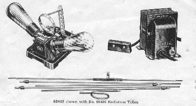

80435 RADIO DEMONSTRATION OUTFIT, Short Wave, Cenco (Patent No. 1,918,402), for demonstration of the fundamental principles of radio transmission and reception, and for teaching the principles of electromagnetic radiation. The apparatus is designed to give clear-cut and convincing demonstrations of the various phenomena associated with radio and electro-magnetic waves. The apparatus consists of a transmitting outfit and a receiving outfit. The transmitter is a high frequency vacuum tube oscillator with two power tubes of the "10" type with a fixed frequency of 85,000,000 cycles per second. The oscillator receives its power supply from a transformer connected to the 110 volt 60 cycle line. The transformer has two windings, one of which energizes the filaments of the power tubes, while the other supplies the plate voltage. A three-conductor flexible cord with special connecting plug which fits three spring jacks on the oscillator unit transmits the current from the transformer to the oscillator. The oscillator has all its parts compactly mounted on a molded Bakelite base, 11 by 16 cm. The condensers are mounted within the base to which the tube sockets are attached and the inductance of the circuit is provided by a copper loop about 7 cm in diameter. A switch mounted on the transformer permits quickly cutting off the power when this is desirable. Horizontal sending antenna may be connected directly to the ends of the inductance loop. A coupling loop to which the vertical sending antenna may be connected is also provided. In this manner the transmitted waves may be polarized either horizontally or vertically. Both sets of sending antenna may also be used simultaneously.
The receiver is of the simplest possible form. It consists of a simple linear oscillator which is a straight conductor connected at its middle through a small incandescent lamp. Its length may be adjusted by means of copper rods telescoping into its ends. When the length is properly adjusted so that it oscillates at the frequency of the transmitter, the lamp glows brilliantly when held within a meter of the transmitter and continues to glow at several meters.
The Cenco Radio Demonstration Outfit provides the means for nearly all the demonstrations necessary in the beginning and intermediate courses in physics on the subject of radio waves. The apparatus is very easy to use, since there are no adjustments to make:. As soon as the power supply is turned on the transmitter oscillates and continues to do so until the power is shut off. All parts of the transmitter except the inductance and its terminals are guarded to protect the operator from contact with the high voltage current. The inductance loop carries high frequency, contact with which produces no sensation whatever and is entirely harmless.
The experiments listed below may be performed either with this apparatus alone or with simple accessories.
1. High Frequency Oscillation Phenomena. Transmission of high frequency energy through the body to light incandescent lamps. Demonstration of potential node at the midpoint of inductance loop, and points of maximum potential at the ends of the inductance loop, demonstrated with the aid of No. 80439 Exploring Lamp or one of the Neon Bulbs, Nos. 80461 or 84485.
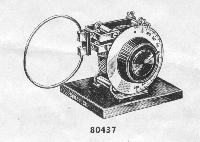
2. Measurement of Frequency. This is accomplished with the aid of No. 80437 Wave-Meter.
3. Standing Waves on Wires. This is the well-known Lecher Experiment in which the wave- length can accurately be measured. No. 80439 Exploring Lamp or Neon Bulb Indicator is used.
4. Transmission of Radio Waves, using horizontal or vertical sending antenna. Glowing. of the indicating lamp on the receiving antenna or linear oscillator demonstrates the transmission of the waves.
5. Polarization of Radio Waves. Shown by rotating the receiving antenna in a vertical plane. When the receiving antenna is parallel to the sending antenna the light responds; when the antennae are at right angles to each other there is no response.
6. Composition of two Plane Polarized Waves. In this case both sending antennae are employed. When the receiving antenna is placed at 45 degrees there is no response in the plane in which the waves from the sending antennae interfere. Maximum response occurs in the other 45 degree position.
7. Demonstration of Coupling. The vertical sending antenna with its coupling coil is used and the receiving antenna held parallel to it. As the coupling loop is moved nearer the inductance on the antenna, the receiving lamp becomes brighter. When at right angles there is no response.
8. Measurement of Electro-Magnetic Field Intensity. If in place of the light in the receiving,- antenna a thermogalvanometer like No. 82665 is used with No. 80451 Terminals to which the receiving antenna may be attached, the response to radiation of proper wave length is much more sensitive and indications of the meter are roughly proportional to intensity of the received radiation. By this method lines of equal intensity within the room may be located and plotted.
9. Transmission of Polarized Waves Through a Screen. The screen may be constructed of parallel copper wires on a wood frame. When the screen is, placed between transmitter and receiver waves are transmitted in one plane but not in the plane at right angles to the first.
10. Standing Waves in Space. For this purpose a reflecting screen made of No. 80449 Sheet Copper is used. When the transmitter with sending antenna is placed at the proper distance from the screen the space between the transmitter and screen when explored with the receiving antenna will be found to have a number of. standing waves in it.
11. Standing Waves an a Solenoid. This experiment is performed with the addition of No. 80453 Standing Wave Tube.
Complete with two pairs of transmitting antennae, vertical coupling turn, tunable receiving antenna with flashlight bulb detector, power transformer, and complete directions for per- forming experiments, but without vacuum tubes
Each $30.00
80436 Radiotron Tube, "10" type, tested in our laboratories for satisfactory oscillation in No. 80435 Radio Demonstration Outfit ...
Each 2.00

80437 Wave-Meter, especially designed for use with No. 80435 in measuring the frequency of the short wave oscillator. The condenser consists of four stationary plates and three movable plates of brass, soldered together, with metal end plates. The rotor is counterbalanced. The condenser is so well shielded by the metal end plates that the effect of hand capacity is negligible. The maximum capacitance is 50 mmf. The single turn coil is made of %-inch copper tubing silver- plated for high conductance. The 4-inch dial is graduated over half its circumference with a scale of equal parts reading from 0 to 100. A calibration chart in a protecting frame with celluloid window is supplied from which the correct wave-length corresponding to any setting of the dial may be readily obtained. The range of the meter in wave-lengths is from 3 to 5 meters (60,000 to 100,000 kilocycles) by 0.05 meters. On a black wood base
Each 16.00
80438 Mounting Clip, for attaching a No. 80447 Flashlight Bulb to the loop of No. 80437 Wave Meter, in order to determine when the wave-meter is properly tuned to the sending outfit
Each .75
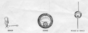
80439 Lamp, Exploring, Mounted, with conducting handle, for exploring conductors carrying high frequency. Consists of an incandescent bulb of suitable characteristics, to the central contact in the base of which is soldered a V-shaped wire guide; the bulb is mounted in a conducting handle. By touching such a conductor with the V-shaped piece while the lamp is held by the handle, the presence of high frequency potential relative to the body is shown by the fact that the filament lights. It can be used for example, with No. 80435 Radio Demonstration Outfit. By applying it, as mentioned, to the loop, away from the central point of the latter, the filament glows brightly as a result of current passing through the lamp and the body of the person holding it. If the lamp is moved along in contact with one of the Lecher wires (see description of No. 80435) it glows brightly at potential "loops" and is dark at potential "nodes." In this manner the standing waves are beautifully shown. It can also be used with No. 80700 Tesla Apparatus to demonstrate passage of high frequency current through the body ----------------------------------------------------------------- ---------------------------
Each $1.50

8.0441 Extra Receiving Antenna with single lamp indicator. May be used simultaneously with one sup- plied with the outfit to show reception at various places at the same time ------------------
Each 3.50
80443 Linear Oscillator, with indicator lamps for showing distribution of current in a tuned linear oscillator. Along the length of the oscillator are mounted seven flashlight bulbs through which the current must pass. This gives a vivid demonstration of the fact that the current is maximum at the middle point of the oscillator and falling off toward the ends. Complete with seven No. 80447 Bulbs Each 7.50
80447 Incandescent Bulbs, Miniature Base, for use with Nos. 80441 and 80443. For 6.3 volts, 0.15 amp. ..........................................................................................
Each .10
80449 Sheet Copper, No. 36, in roll, containing about 100 square feet or sufficient for the construction of a reflecting screen for standing wave demonstrations Per roll 16-00
82665 Thermo-Galvanometer, Weston Model 425, for use in measuring the electromagnetic field intensity at various distances from the oscillator and in detecting the nodes and anti-nodes in the standing waves by reflection. A full scale deflection represents about 115 milliamperes. The safe current carrying capacity is 500 milliamperes -----
Each 3.50
80451 Meter Terminals, for use with No. 82665 Thermo-Galvanometer to provide for attaching adjust- able antennae to the latter. These terminals are to be fastened to the Thermo-Galvanometer by means of hexagonal nuts provided on the back of the instrument. For antennae those supplied with the tunable receiving antenna of No. 80435 may be used. These terminals are designed to fit the telescoping tubes supplied with receiving antenna which is part of No. 80435 Outfit. Adjustment in length of the antennae attached to the meter tunes the system to resonance, and this combination makes a very sensitive detector of the waves radiated from the transmitting unit
Per pair .60

80453 STANDING WAVE TUBE, for use with No. 80435 Radio Demonstration Outfit, for making striking demonstrations of standing radio waves. Consists essentially of an elongated helix, wound with many turns of fine copper wire uniformly spaced. The helix is of such dimensions and electrical characteristics that its natural oscillation frequency is closely in resonance with the frequency of No. 80435 Oscillator. Consequently, when the standing wave tube is coupled with the loop of No. 80435 Oscillator, which is accomplished by placing it in proximity with the loop, very powerful resonant waves are set up on the standing wave tube. The length of the tube and of the wire constituting the helix results in a series of approximately eight or nine stationary waves which can be detected with No. 80457 Neon Wand or with Nos. 80439 Exploring Lamp or 84485 Neon Bulb. The Neon Wand, however, makes a very much more striking demonstration which can be seen from the remotest points of a lecture room, as a result of large size and high intensity of the illuminating tube. The waves are exactly similar to the stationary waves in an open-ended organ pipe. They consist of a series of voltage nodes and anti-nodes, each pair of anti-nodes including between them Y2 wave length. At each open end of the tube there is 1/4 wave with an anti-node at the end. In use, the tube is supported at its one end by the insulating support provided, which is clamped at the uppermost point of the oscillator loop. About 5 cm of the winding is allowed to project through the loop. The other end of the tube is supported in the stand provided, care being taken to insure that clamping be done in the free glass portion of the tube and not on the winding. With clamps, supports, and directions for use.
Each $5.00
80457 NEON WAND, Cenco, for use in demonstrations with No. 80453 Standing Wave Tube and other sources of high frequency oscillations. The Cenco Neon Wand is a discharge tube containing neon gas at reduced pressure, with external "electrodes" only. When held in the hand, and placed in a high frequency field, near the short wave oscillator (No. 80435), or near the standing wave tube (No. 80453), it bursts into an intense neon glow. It may be used also as a tuning indicator. Length, 10 inches; diameter of glow tube, 1/2 inch
Each 2.00
80459 Condenser Plates, for increasing the wavelength of the oscillator of No. 80435 to about 6.5 meters, or reducing the frequency from about 85 megacycles to about 45 megacycles. These plates have extension lugs on them which fit the antenna sockets, and when in position they ex- tend upward above the single-turn inductance. A slow-motion adjustment consisting of a screw with hard rubber insulation and head, permits precise adjustment of wavelength to be made, using a wavemeter as the reference device. These plates permit some variation of frequency at the lower values. For specific application to the measurement of dielectric constant see No. 70030
Per pair 6.50
80461 Neon Test Lamp, 1/4 watt, for use with No. 80435 Short Wave Demonstration Apparatus for determining whether the outfit is oscillating and for locating positions of maximum and minimum potential. A small clip, soldered to the base, is provided for attachment to No. 80437 Wave-Meter in case it is desired to use this lamp in place of the flashlight bulb when tuning the meter.
Each 1.00
10% discount in lots of 6

84485 NEON GLOW LAMP, Standard Edison Base, 2 Watt, for normal use on 110 volts A. C. or D. C. Can also be operated at a minimum of 50 volts below normal on A. C. and 10 volts below normal on D. C. When used on D. C. only one electrode glows but gives the same energy as do both electrodes on A. C. Can also be used on 220 volts A. C. or D. C. with decreased life. Useful as indicators for remote control of lighting circuits, storage rooms or other dark rooms, as an indicator or pilot lamp to show location of valve controls, alarms, etc. For resistance and capacity check and in testing for grounds, shorts, voltage polarity and frequency. Can also be used in the optics laboratory as a source for visual spectra--.
Each .50
89560 Copper Wire, Bare, No. 24, for the Lecher wire experiment
Per 4 oz. spool .28
Go to the Index Page,
Wesleyan Physics Home Page,
Wesleyan University,
or submit gripes or accolades to Vacek Miglus